chapter seven
Chapter 7. Serial communication
This chapter covers
- What serial communication is, what it can do, and where it gets used
- How to work with asynchronous serial components like GPS modules
- An introduction to the core skills of soldering
- The basics of synchronous serial communication and the most popular protocols for hobby electronics: SPI and I2C
- Building more complex projects by combining multiple serial device components
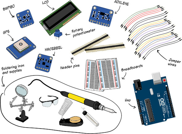
For this chapter, you’ll need the following:
- 1 Arduino Uno and USB cable
- 1 Adafruit Ultimate GPS breakout board
- 1 Adafruit HMC5883L magnetometer (compass) breakout board
- 1 Adafruit BMP180 multisensor breakout board
- 1 Adafruit ADXL345 Triple-Axis accelerometer breakout board
- 1 16x2 parallel LCD module, or, optionally, I2C-enabled Grove RGB LCD module
- 1 rotary potentiometer (for parallel LCD)
- Breakaway male header pins
- Soldering iron and soldering supplies
- Jumper wires
- 2 half-size breadboards
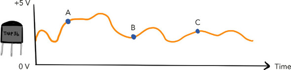
In our experiments so far, we’ve been able to glean some fun but straightforward data about the world around us, such as temperature (figure 7.1) or ambient light intensity. And by listening for variance in a basic digital signal (HIGH vs. LOW), we could tell if a button had been pressed.