A vertex shader is a GPU program that processes vertices before geometry is rasterized. It can move a vertex or use matrix math to project a 3D scene onto the screen. Drawing one triangle means processing three vertices; the resulting fragments are then processed by a fragment shader. section 7.1.2 section 7.4.4
A key job is turning positions into coordinates the rasterizer can use. A vertex shader outputs a four-dimensional position (x, y, z, w) in clip space. Dividing x, y, and z by w produces normalized device coordinates; setting w to 1.0 leaves those components unchanged. Geometry outside clip space is clipped. section 7.4.2
In normalized device coordinates, the center of the screen is (0, 0), the x and y edges are at -1 and +1, and positive y points upward. That differs from screen-space coordinates measured from the window’s top-left corner, where positive y points downward. section 7.4.2
Figure 7.5 Screen space vs. normalized device coordinates
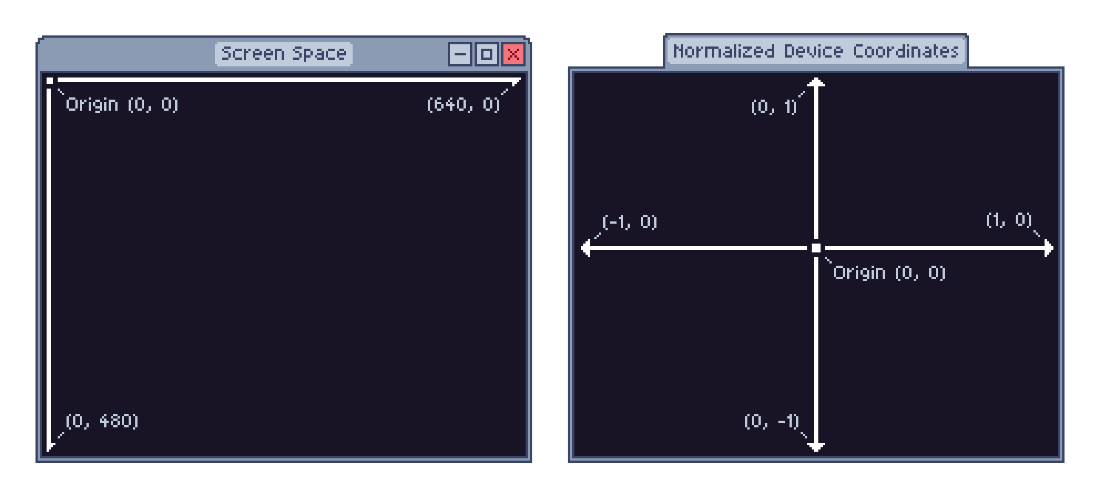
Compare the origins, axes, and screen boundaries of the two coordinate systems. section 7.4.2
A triangle in normalized coordinates
The three positions (-0.5, -0.5), (0.5, -0.5), and (0.0, 0.5) define a triangle around the center of the screen. With w set to 1.0, the coordinate division leaves those x and y values unchanged. section 7.4.2
Listing 7.8 Triangle vertices
const triangle = [_]f32{
    -0.5, -0.5, #1
    0.5,  -0.5, #2
    0.0,  0.5, #3
};
Inspect the triangle positions as a Zig array of floating-point values. section 7.4.2
In OpenGL, a draw call specifies how many vertices to render. Vertex attributes supply per-vertex inputs, usually including position, from buffers. The shader sees one set of attributes at a time, allowing vertex processing to be parallelized. A vertex array object (VAO) preserves attribute state for use with shader programs. section 7.4.4
Listing 7.12 An abstract object
var vao: c_uint = undefined;
c.glGenVertexArrays(1, &vao); #1
defer c.glDeleteVertexArrays(1, &vao); #2
Create a VAO in Zig and pair its OpenGL creation with deferred deletion; vertex data is still needed to configure it. section 7.4.4