A wire pair is two conductors in a network cable that together form an electrical circuit between connected devices. Each conductor connects to a pin in the cable’s 8P8C connectors. section 3.3.2
Ethernet standards use wire pairs differently:
- 10BASE-T and 100BASE-T use two pairs: pins 1–2 and pins 3–6, with one pair carrying each communication direction. section 3.3.2
- 1000BASE-T and 10GBASE-T use all four pairs, or all eight wires. section 3.3.2
- Straight-through cables preserve pin-pair positions; crossover cables connect a device’s transmit pair to the other device’s receive pair. section 3.3.2
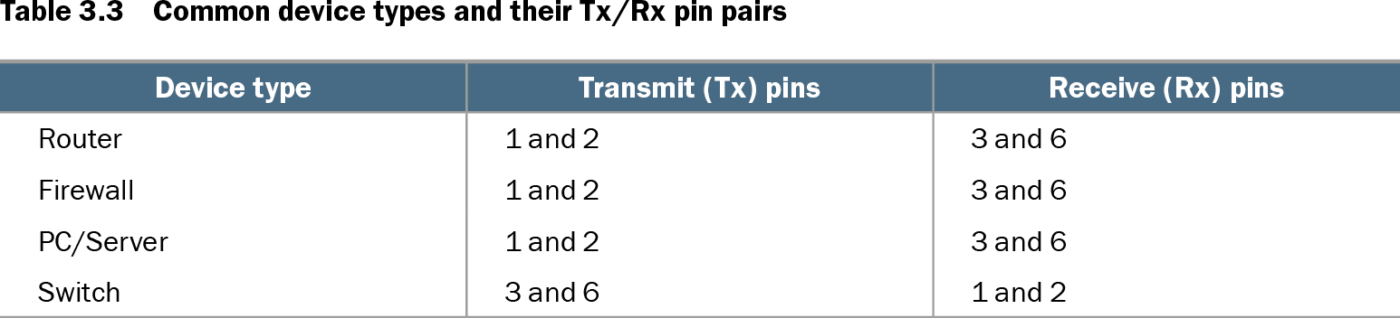
Table 3.3 Common device types and their Tx/Rx pin pairs (view table figure)
| Device type |
Transmit (Tx) pins |
Receive (Rx) pins |
|---|---|---|
| Router |
1 and 2 |
3 and 6 |
| Firewall |
1 and 2 |
3 and 6 |
| PC/Server |
1 and 2 |
3 and 6 |
| Switch |
3 and 6 |
1 and 2 |
Compare transmit and receive pin pairs for routers, firewalls, PCs, servers, and switches. section 3.3.2