SPI (Serial Peripheral Interface)
Overview
SPI, or Serial Peripheral Interface, is a synchronous serial communication protocol that facilitates communication between a master device and one or more slave devices. It was originally developed by Motorola in the 1980s. The protocol is known for its fast data transmission rates, making it a popular choice for applications requiring high-speed data exchange.
Configuration
In a simple SPI configuration involving one master and one slave, as few as three wires can be used for data exchange. These wires include:
- SCK (Serial Clock): A shared clock line managed by the master.
- MOSI (Master Out Slave In): The line for data sent from the master to the slave.
- MISO (Master In Slave Out): The line for data sent from the slave to the master.
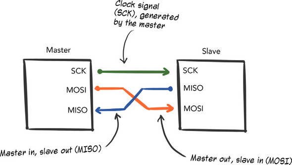 Figure 7.19. In a simple SPI configuration—one master, one slave—as few as three wires can be used for data exchange: a shared clock line (SCK) managed by the master, master-out-slave-in (MOSI), and master-in-slave-out (MISO).
When more devices are added to the SPI bus, at least one additional line, known as the Slave Select (SS) line, is required. Some configurations may require one SS line per slave device.
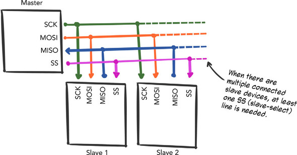 Figure 7.20. When more devices are added, at least one additional line—slave-select (SS)—is needed, though some SPI configurations require one SS line per slave device.
Applications
SPI is widely used in various applications due to its high-speed data transmission capabilities. A common example is the use of SPI in SDCard memory cards, which require fast data transfer between a master device and one or more slave devices.
Another example is the ADXL345 triple-axis accelerometer breakout board from Adafruit, which supports both I2C and SPI interfaces. Although Johnny-Five's support for this board uses the I2C interface, the board can be connected using a four-wire SPI setup.
 Figure 7.27. The ADXL345 triple-axis accelerometer breakout board from Adafruit. It can be connected to an I2C bus (via SDA and SCL pins) or, with some pins doing double duty as noted in the image, a four-wire SPI setup (via CS, SDO, SDA, and SCL pins).
Advantages
The primary advantage of SPI is its ability to achieve high data transmission rates. Additionally, the receive hardware for SPI is significantly simpler compared to a UART, making it an efficient choice for many embedded systems and hardware hacking projects.
FAQ (Frequently asked questions)
What is SPI in the context of serial communication?
What is SPI known for?
How many wires are needed in a simple SPI configuration?
What are the roles of the wires in a simple SPI setup?
What is an example of SPI usage?
How many wires does SPI require?
Can multiple devices communicate over SPI?