A controlled-on-zero gate applies a target operation if and only if every control qubit is in the |0⟩ state. It is also called an open-controlled gate, reflecting its circuit symbol. Basis components whose control pattern is not all zero remain unchanged; linearity extends this conditional behavior to superpositions. section 2.3.1
A controlled-on-zero version can be built from an ordinary controlled gate: apply X to each control, apply the ordinary controlled target operation, then apply X again to restore the controls. This converts the all-zero condition into the usual all-one control condition without changing the controls afterward. section 2.3.1
Use controlled-on-zero gates to split an operation by control branch:
- Prepare the branch associated with control |0⟩ while leaving the |1⟩ branch unchanged. section 2.3.2
- Combine an operation A for control zero with an operation B for control one to implement a block-diagonal matrix diag(A, B). The two conditional operations commute because they act on different control patterns. section 3.5.2
- Recursively prepare an n-qubit state by conditioning the preparation of the remaining qubits on whether the first qubit is |0⟩ or |1⟩. section 2.5.1
Two-qubit state preparation
To prepare a0|00⟩ + a2|01⟩ + a1|10⟩ + a3|11⟩, first prepare the control qubit with amplitudes √(a0²+a2²) and √(a1²+a3²). Then apply a controlled-on-zero one-qubit preparation to transform the control-|0⟩ branch using a0 and a2, and an ordinary controlled preparation to transform the control-|1⟩ branch using a1 and a3. section 2.3.2
In Qiskit, create a controlled custom gate with control(1, ctrl_state=0) and append it with control qubits listed before target qubits. Transpile circuits containing custom and controlled gates before running them on a simulator or device. In Q#, a controlled specialization enables ApplyControlledOnBitString with [false] or ApplyControlledOnInt with 0. section 2.3.3 section 2.3.4
Figure 2.4 Preparing a two-qubit state. Each set of four bars represents the amplitudes of the basis states: from left to right, \(\ket{0}\), \(\ket{1}\), \(\ket{2}\), and \(\ket{3}\). Light bars indicate zero amplitudes (basis states not present in the superposition state), dark bars indicate nonzero amplitudes (positive or negative). We prepare the least significant qubit in a superposition state and then adjust the state of the most significant qubit depending on the state of the least significant qubit using controlled gates. The left path handles the case of the least significant qubit being in the \(\ket{0}\) state, and the right path handles the \(\ket{1}\) state. Striped bars represent the amplitudes of the basis states that are involved in each path.
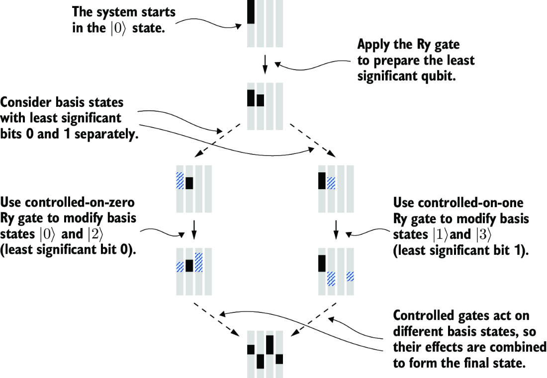
Inspect the two conditional paths: one adjusts amplitudes for the control-|0⟩ branch and the other for the control-|1⟩ branch. section 2.3.2