A crossing edge is involved in a geometric intersection between two graph edges at a point that is not a shared endpoint. In a graph drawing, crossings can obscure relationships and reduce readability. section 15.1 section 15.3
The concept matters when embedding graphs in the two-dimensional plane. Planar graphs can be drawn with no crossings; non-planar graphs require one or more, so layouts aim to minimize them. section 15.3 section 15.0
Use crossing edges to reason about graph layouts:
- Treat crossings as a layout cost when displaying flow charts, UML diagrams, PERT charts, or other visual graphs. section 15.1
- Compare embeddings by their number of crossings rather than by the abstract graph alone. section 15.3
- Distinguish a genuine edge crossing from edges meeting at a common vertex. section 15.1
Printed circuit board layout
Model electronic components as vertices and conductive tracks as edges. A crossing between tracks can make the embedding less suitable, so the layout seeks fewer intersections while respecting the board’s geometric constraints. section 15.0
Figure 15.1 An example of an electronic circuit, and a graph embedding from which the circuit’s layout may have been derived. Looking at the graph, all electronic components have a vertex dual (with different shaded colors by type), and the joints have been modeled with vertices on the graph (to cope with the fact that we need to restrict to horizontal and vertical segments for conductive tracks).
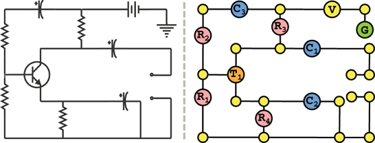
Use the circuit embedding to connect crossing edges with a concrete layout problem involving components, joints, and conductive tracks. section 15.0