A fiber-optic cable transmits data as light through a glass fiber instead of electrical signals through copper. Its longer reach makes it useful between floors, buildings, and across WAN connections, though it costs more than copper UTP. section 3.4 section 3.4.2
Key characteristics include:
- A core carries light, reflective cladding guides it, and buffer and outer jacket protect the cable. section 3.4.1
- A typical connection uses separate transmit and receive fibers connected through a modular SFP transceiver in an SFP port. section 3.4.1
- Multimode fiber uses a wider core with LED transmitters and supports distances of several hundred meters. section 3.4.1
- Single-mode fiber uses a narrow core with laser transmitters and supports distances reaching tens of kilometers, at greater transceiver cost. section 3.4.1 section 3.5
- Handle fiber carefully: sharp bends can damage the glass or leak light and weaken the signal. section 3.4
Choosing fiber for an infrastructure link
A switch on one floor can connect to a router in another building using fiber and SFP transceivers. Verify that one device’s transmitter connects to the other device’s receiver. Choose MMF for shorter infrastructure distances or SMF when the link requires much greater reach; use copper UTP for ordinary switch-to-PC connections when 100 meters is sufficient. section 3.4.1 section 3.4.2
Figure 3.9 The typical structure of a fiber-optic cable. An outer jacket (4) and buffer (3) serve to protect and contain the inner components. A layer of reflective cladding (2) helps carry the light signal along the glass core (1).
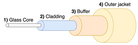
Use the cable anatomy diagram to identify the core, cladding, buffer, and outer jacket. section 3.4.1
Figure 3.10 Light travels down an MMF cable at multiple angles (modes), whereas light travels down SMF cables at a single angle.
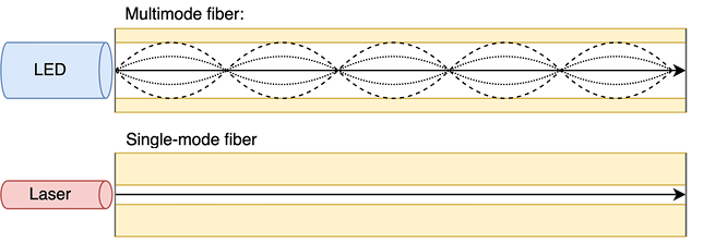
Use the light-path diagram to compare multiple modes in MMF with the single mode used by SMF. section 3.4.1