A UML class diagram makes an object-oriented design discussable before coding, reducing accidental complexity while leaving room for judgment rather than prescribing a perfect solution. section 1.3
A subsystem diagram can show:
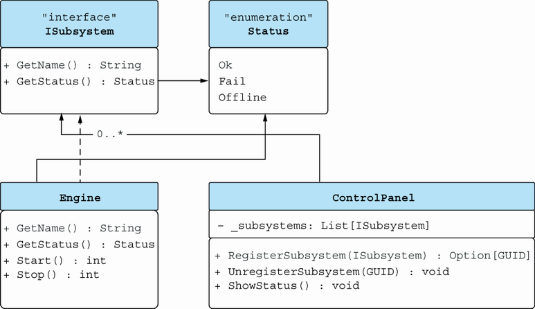
- An interface, such as ISubsystem. section 1.3
- An implementation, such as Engine, and a client class, such as ControlPanel. section 1.3
- Supporting domain elements, such as the Status enumeration, alongside relationships among classes. section 1.3
Engine control subsystem
A high-level model represents starting and stopping engines, bookkeeping subsystems, and related operations through an interface, its implementation, a consuming control panel, and status information. section 1.3
Figure 1.7 OOD class diagram for the engine control subsystem
Inspect the engine control subsystem’s UML organization as a visual complement to the element-by-element description. section 1.3