A 3D modeling primitive is a geometrically simple shape represented by a minimal parameter set. Its definition describes shape only, separately from pose: position and orientation. A cylinder, for example, needs radius and height; a cuboid needs width, length, and height. This compact representation is useful when a robot link or object is simple enough to describe directly rather than as a detailed surface model. section 6.1.5
Figure 6.12 Simple geometric shapes, such as circles, rectangles, and cylinders, are mathematically defined by a minimal set of parameters, such as length, radius, and angle.
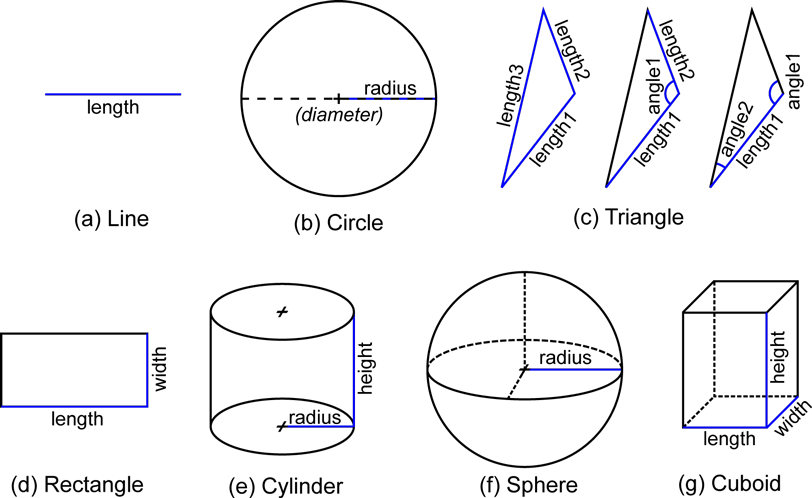
Simple shapes expose the core idea: a small number of lengths, radii, and angles uniquely defines each primitive. section 6.1.5
Common parameterizations include:
- A line uses length; a circle or sphere uses radius. section 6.1.5
- A rectangle uses width and length, while a cuboid adds height. section 6.1.5
- A cylinder uses radius and height. section 6.1.5
- A triangle can use three side lengths, two sides and their included angle, or two angles and the included side. section 6.1.5
Parameterized formulas make primitives operational rather than merely descriptive. They can render a shape and its outline, test whether a point lies inside it, and test whether two shapes intersect. For a circle centered at the origin, the radius defines both its equation and its boundary points: iterating an angle t through a full turn yields x = r cos(t) and y = r sin(t). A point is inside or on that circle when its distance from the origin is no greater than r. section 6.1.5
Robot-link geometry in URDF
Use primitives for simple robot links and meshes where shape detail requires them. A URDF link can contain box geometry for visualization, with dimensions supplied directly in the geometry element. Keep visualization and collision shapes separate when appropriate: each can use a different shape suited to its purpose. Position the link geometry relative to its link frame with an origin, then connect links through joints to form the robot’s kinematic tree. section 6.1.6 section 6.1.6
Listing 6.3
<robot name="snackbot"> #1
  <link name="base_link"> #2
    <visual name="base_link_visual1"> #3
      <origin xyz="0.05 0.05 0.0078" rpy="0 0 0"/> #4
      <geometry> #5
        <box size="0.1 0.1 0.0156"/>
      </geometry>
      <material name="blue"> #6
        <color rgba="0 0 0.8 1"/>
      </material>
    </visual>
    <visual name="base_link_visual2"> #7
      <origin xyz="0.05 0.05 0.1421" rpy="0 0 0"/>
      <geometry>
        <box size="0.05 0.05 0.253"/>
      </geometry>
      <material name="cyan">
        <color rgba="0 0.8 0.8 1"/>
      </material>
    </visual>
  </link>

  <joint name="joint1" type="revolute"> #8
    <parent link="base_link"/> #9
    <child link="link1"/>
    <origin xyz="0.050 0.050 0.268" rpy="0 0 0"/> #10
    <axis xyz="0 0 1"/> #11
    <limit lower="-1.57" upper="1.57" effort="10" velocity="10"/> #12
  </joint>

  ...

  <link name="link2">
    <visual name="link2_visual">
      <origin xyz="0 0 0" rpy="0 0 0"/>
      <geometry>
        <mesh filename="package://rfp_snackbot/models/snackbot/link_2_manual.stl"/>
      </geometry>
      <material name="yellow">
        <color rgba="0.8 0.8 0 1"/>
      </material>
    </visual>
  </link>

  ...
</robot>
The URDF fragment shows a base link assembled from box primitives, each with explicit dimensions and a local origin. section 6.1.6
Primitives trade geometric detail for directness. Constructive solid geometry can combine them through union, difference, and intersection to create more complex solids. When an object needs a detailed surface, use a mesh: connected polygons, typically triangles defined by vertices, edges, and faces. Other representations serve different sensing or modeling needs: voxel grids discretize volume, while point clouds record visible sampled surface points without explicit connectivity or volume. section 6.1.5 section 6.1.5