A Bridge Protocol Data Unit (BPDU) is an STP control message that switches exchange to share topology information and prevent Layer 2 loops. BPDUs are sent every 2 seconds and carry the information switches use to choose the root bridge and port roles. section 14.3.1 section 14.6
Switches use BPDU information to make three main STP decisions:
- Elect one root bridge using the lowest bridge ID (BID). A BID contains bridge priority and a MAC address. section 14.3.1
- Select one root port on each non-root switch using the lowest root cost, then the lowest neighbor BID, then the lowest neighbor port ID. section 14.3.2
- Select one designated port per segment using the lowest root cost and then the lowest BID. section 14.3.3
- Carry root-cost information: the root bridge advertises cost 0, and downstream switches add the cost of the receiving port before forwarding the BPDU. section 14.3.2
Reading a spanning-tree result
When SW3 is configured with priority 24576 for VLAN 1, its BID becomes 24577 plus its MAC address, making it the root bridge. Other switches use the BPDUs from SW3 to select their best root ports. On the root bridge, all ports are designated and send BPDUs; non-designated ports do not forward normal frames but continue listening for BPDUs. section 14.3.1 section 14.3.3
A newly enabled port first listens for BPDUs while STP decides its role. Root or designated ports then learn MAC addresses before forwarding; a non-designated port enters blocking and continues monitoring BPDUs. section 14.4.1
Use show spanning-tree to inspect the root and local BIDs, port roles, states, and costs. Standard STP uses a 2-second hello timer, 15-second listening and learning periods, and a 20-second max-age timer. section 14.4.2 section 14.6
Figure 14.5 SW1, SW2, SW3, and SW4 boot up simultaneously, each switch declaring itself the root bridge. The switches send BPDUs out of their ports, containing information such as the switch’s own BID and the BID of the switch it believes to be the root bridge (itself, in this case).
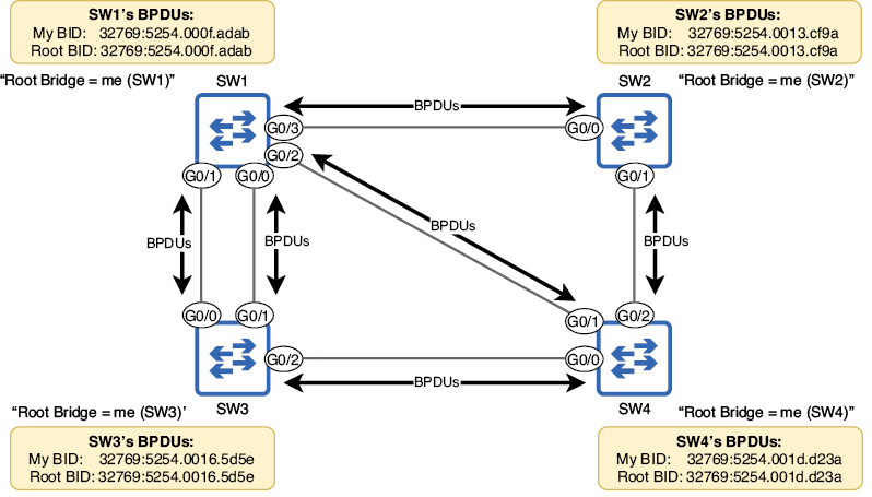
Follow the boot-up scenario to see switches initially declare themselves root bridges by sending BPDUs containing matching local and root BIDs. section 14.3.1