A UML sequence diagram maps one runtime request from arrival to response. Participants become vertical lifelines, messages become horizontal arrows, and time flows from top to bottom, making handoffs, dependencies, and failure points visible. section 8.5
Use the diagram as a focused trace rather than a complete system map:
- Choose one endpoint and inspect its handler plus imports. section 8.5
- Generate Mermaid sequenceDiagram syntax so the result can render beside the code. section 1.3.1 section 8.5
- Keep the participant count small enough to preserve the flow; four or five participants usually remain readable. section 3.4.2
- Separate synchronous work that blocks the response from asynchronous work that fans out afterward. section 8.5
- Treat the output as a claim to verify against the implementation, not as an unquestionable explanation. section 1.3.1
Tracing a booking endpoint
For Cal.com's POST /api/book/event, the diagram follows six lifelines from the client through the gateway, booking service, and Postgres to external APIs and notifications. The flow distinguishes checks and writes completed before 201 Created from asynchronous notifications and other work triggered afterward. section 8.5 section 8.6
POST /api/book/event sequence. Six service lifelines, time flowing top to bottom. Everything above the 201 Created runs while the user waits; everything below fans out async.
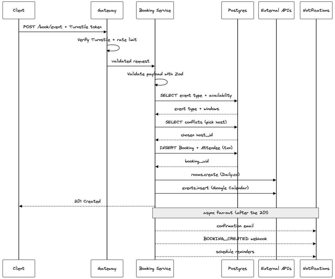
Use the rendered endpoint trace to inspect lifelines, message order, the 201 Created boundary, and asynchronous fan-out at a glance. section 8.5