A controlled quantum operation applies a unitary U to target qubits only when its control qubits match a specified pattern. In the standard all-ones form, U acts when every control is |1⟩; otherwise the basis state is unchanged. Linearity extends this rule to superpositions. A CNOT is the simplest case: a controlled X with one control and one target. section 2.3.1
Control choice is part of the operation. For two qubits, either the most or least significant qubit can control U, and a gate can be controlled on |1⟩ or on |0⟩. Matrix layouts therefore depend on the basis-index convention: Qiskit uses little-endian bit strings, while Q# uses big-endian ones. section 3.5.1
Figure 3.4 The row and column indices of \(4 \times 4\) matrices. The indices are written in binary using little-endian notation: the least significant bit is written first. You can see that the top-left and bottom-right blocks group the elements for which the most significant (the last) bit of the row index equals that of the column index: for the matrix \(A\) in the top-left block, the most significant bit is \(0\), and for the matrix \(B\) in the bottom-right block, the most significant bit is \(1\).
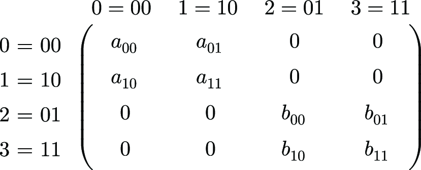
Inspect the binary row and column indices to see why a controlled operation occupies an identity block for one control value and an operation block for the other. section 3.5.1
Controlled operations provide a direct construction tool for structured unitaries:
- Implement a block-diagonal matrix diag(A, B) by combining controlled B with controlled-on-zero A on the same control. The operations commute because their control patterns are disjoint. section 3.5.2
- Separate a two-qubit CS matrix into unitary pieces M0 and M1, then apply controlled M1 and controlled-on-zero M0. section 3.6.1
- Extend a controlled single-qubit operation to n qubits by using n−1 controls whose little-endian pattern selects the affected pair of basis states. section 3.9.1
Making a global phase observable
A controlled operation can turn an otherwise unobservable global phase into a relative phase. Prepare |++⟩, apply a controlled unknown X-like gate, and compare the result: controlled X leaves the state unchanged, while controlled −X produces a relative minus sign on the control qubit. This supports distinguishing the two operations through a suitable measurement sequence. section 5.1.1
Converting a phase oracle into a marking oracle
Prepare an ancilla in |0⟩, apply H, use it as the control for a controlled phase oracle, then apply H again. A marked input gives the ancilla |1⟩; an unmarked input gives |0⟩, producing the marking-oracle behavior. section 7.1.1