A state transition changes an object from one state to another when the values of its member variables change. Member functions determine the runtime behaviors that cause those changes. section 1.8
A UML state diagram makes one object’s runtime behavior visible: rounded boxes represent states, arrows represent transitions, and labels identify the events or conditions that cause them. The diagram helps check whether a class has the necessary member variables and member functions. section 4.5
A transition may be caused by an external action, an internal operation, or a condition:
- Starting a car engine transitions it from parked to idling; accelerating can then transition it to a state characterized by a new speed and heading. section 4.5
- A ticket machine transitions from READY to VALIDATING when a customer inserts a card, then to TICKET_SOLD when validation succeeds. section 13.1
- An invalid card returns the machine to READY; taking the last ticket transitions it to SOLD_OUT, which has no outgoing transitions. section 13.1
- A student-enrollment diagram can show decisions, branches, merges, forks, and joins around the transitions involved in enrolling in a course. section 4.5
When many actions depend on the current state, the State Design Pattern assigns each state its own class. The current state object handles every action and returns the next state; an unreasonable action can return the current state unchanged. This keeps state-specific behavior encapsulated, makes the current state explicit, and reduces dependencies between states. section 13.1.1 section 13.1.3
Ticket-machine transition trace
With three tickets remaining, inserting a card produces READY → VALIDATING. Checking a valid card produces VALIDATING → TICKET_SOLD. Taking the ticket decreases the count and returns to READY. Taking the final ticket instead produces TICKET_SOLD → SOLD_OUT.
Figure 4.14 A UML state diagram that shows the state changes of a Car object during run time. Each box represents a state, and each arrow represents a transition from one state to another. Each transition is labeled with the behavior (event) that causes the transition. Such a diagram allows us to visualize what happens to a particular object during run time and helps to ensure that we designed the class with the correct member variables and member functions.
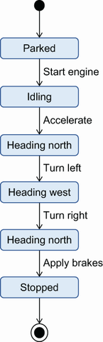
Use the UML diagram to trace the Car object’s states, identify the event on each transition, and check whether the class design supports the visible behavior. section 4.5