A network topology is a directed acyclic graph that defines how records move from Kafka source topics through processing steps to output topics. It makes a streaming application’s data flow explicit. section 8.3.3
A topology connects three kinds of nodes:
- Source nodes read records from input topics. section 8.3.3
- Processing nodes filter, transform, aggregate, or otherwise handle records; stateful operations can use linked state stores. section 8.3.3
- Sink nodes publish processed records to output topics. Edges define the flow between nodes, in memory or through Kafka topics. section 8.3.3
Kafka Streams builds the graph automatically when application logic uses DSL functions. For custom logic, such as calling an external anomaly-detection service, developers can define the topology programmatically and implement reusable Java processors. These can access state stores, schedule actions, or use the Kafka client API. section 8.3.3
Figure 8.9 Internally, the Kafka Streams application is represented as a graph. Events flow from input topics through source nodes, are processed by processing nodes, and are finally published to output topics via sink nodes.
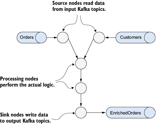
Follow the path from input topics through source and processing nodes to output topics. section 8.3.3
At runtime, each Kafka Streams task combines an instance of the topology with input-partition assignments and its state stores. Tasks can run on different threads or instances; a failed task’s work can be reassigned. Each event traverses the processing graph before the next is consumed. section 8.3.4
Topology behavior can be tested without a running Kafka cluster using TopologyTestDriver: supply records through test input topics and check output topics. Tests can also simulate time and inspect intermediate state. section 10.3.1