Multiprotocol Label Switching (MPLS) connects enterprise LANs across a service-provider WAN, allowing offices to reach systems hosted at remote sites such as a data center. section 16.1
MPLS forwards packets using a fixed-length label rather than relying solely on destination IP addresses. A provider-edge router inserts the additional header between the Layer 2 and Layer 3 headers; routers then forward traffic along a predetermined path. Because the label can carry different packet types, MPLS is often called a Layer 2.5 protocol, although modern deployments usually carry IPv4 or IPv6. section 16.1.2
Identify the router roles in an MPLS WAN:
- Customer edge (CE) routers sit at customer premises and connect the customer network to the provider network; customers typically control them. section 16.1.2
- Provider edge (PE) routers connect customer networks to the provider network and assign or remove MPLS labels. section 16.1.2
- Provider (P) routers operate inside the provider network and forward labeled packets without directly connecting to customer networks. section 16.4
Unlike a leased line, which provides a dedicated connection between two sites, MPLS uses shared provider infrastructure for multiple customers. Labels support traffic segregation through virtual private networks, including Layer 2 VPNs, where the provider network is transparent to CE routers, and Layer 3 VPNs, where CE routers form dynamic-routing relationships with PE routers. section 16.1.2 section 16.4
Figure 16.1 An enterprise WAN connecting four offices and a data center via a service provider’s network infrastructure
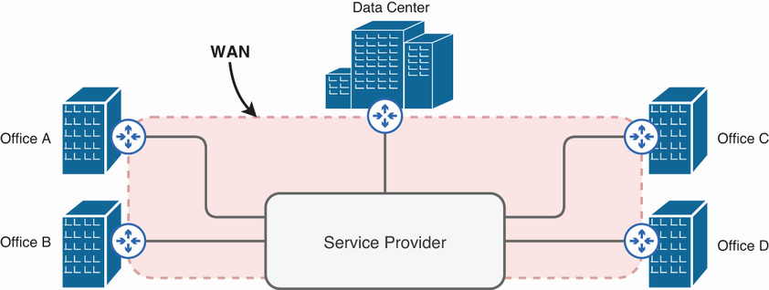
Use the WAN topology to identify enterprise sites, the data center, and the provider network boundary. section 16.1

Inspect the label position between the Layer 2 and Layer 3 headers. section 16.1.2
Figure 16.4 Two customers connect their remote sites via a service provider’s MPLS infrastructure.
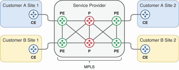
Compare multiple customers sharing one provider MPLS infrastructure. section 16.1.2
Figure 16.5 Two customers connect their remote sites using a service provider’s MPLS L2VPN service. PE and P routers are not shown.
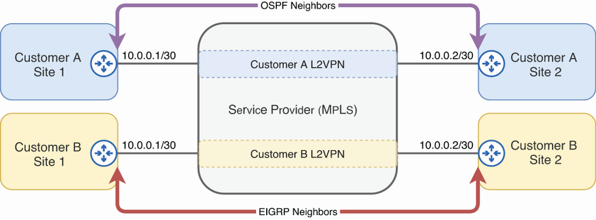
Visualize an MPLS Layer 2 VPN between customer sites. section 16.1.2
Figure 16.6 Two customers connect their remote sites using a service provider’s MPLS L3VPN service. CE routers form dynamic routing protocol neighbor relationships with PE routers.
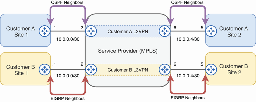
Visualize an MPLS Layer 3 VPN and CE-to-PE dynamic-routing relationships. section 16.1.2