Power over Ethernet (PoE) delivers electrical power and data through the same Ethernet UTP cable, eliminating separate power cables for supported devices. It reduces installation cost and clutter and allows placement where outlets are unavailable. The switch is the Power Sourcing Equipment (PSE); the powered device (PD) may be an IP phone, camera, wireless access point, badge reader, or door lock. section 10.1.2
Protective PoE startup proceeds through four stages:
- Detection applies low voltage to determine whether the connected device supports PoE. section 10.1.2
- Classification assesses the PD’s power requirement and reserves the needed amount from the switch’s available supply. section 10.1.2
- Startup supplies the appropriate voltage; normal operation continues delivery while monitoring current for safe, consistent power. section 10.1.2
Verify power and enforce policing
Use show power inline to inspect the power budget, port state, device, class, and maximum allocation. In the example, the switch has 124.0 watts available, uses 30.8 watts, and allocates 15.4 watts to each class 3 access point. Configure interface-range power policing with power inline police, then verify it with do show power inline police; the displayed cutoff power is 15.4 watts. section 10.1.2
Figure 10.3 SW1, the PSE, supplies electrical power to IP phones (PDs) using PoE.
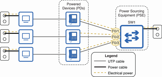
Use the figure to visualize the switch as PSE and connected IP phones as PDs. section 10.1.2