An entity-relationship (E-R) diagram is a visual blueprint of a database. Boxes represent entities, lines represent relationships, and relationship symbols show rules such as cardinality. It models the schema, not the stored records: millions of rows still appear as one entity. section 5.2 section 3.10
Build a useful first draft in a few practical steps:
- Turn requirements into simple subject-verb-object sentences, such as “A user makes purchases” and “A purchase contains products.” section 5.3
- Treat the nouns as entities and connect pairs of entities related by the verbs. Leave attributes out of the first draft if they distract from the relationships. section 5.3 section 4.1
- Assign each relationship a cardinality: one-to-one, one-to-many, or many-to-many. In Crow’s Foot notation, a crow’s foot marks the many side. section 5.10 section 5.5
- Resolve many-to-many relationships with a junction table containing both entities’ primary keys, then review weak entities and foreign-key placement. section 5.10
The Sci-Fi Collective store
Start with users, purchases, products, reviews, and payment methods. Connect User to Purchase because a user can make multiple purchases while each purchase belongs to one user. Connect Purchase to Product because each purchase can contain several products and each product can appear in multiple purchases; represent that many-to-many relationship through a junction table. Similarly, connect User to Review and Product to Review, while requiring that a user bought a product before reviewing it. section 5.3 section 5.10
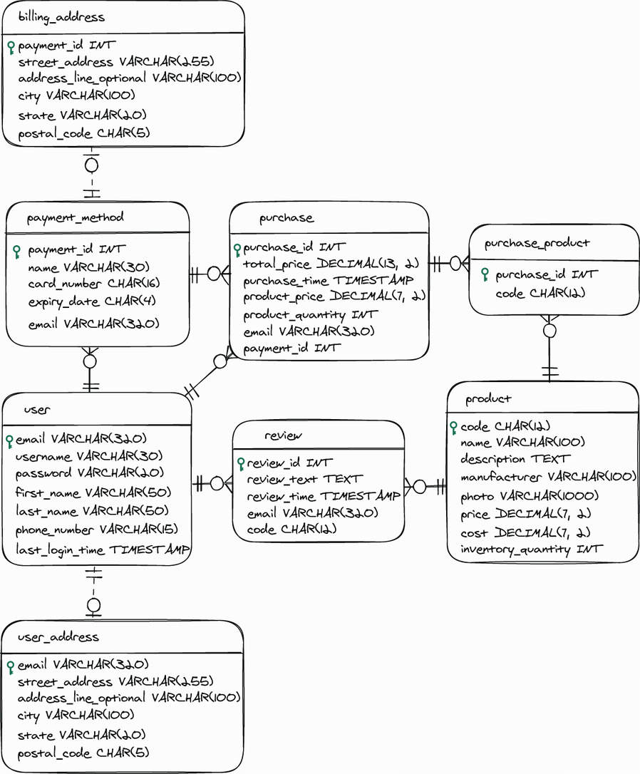
Inspect the visual model to see entities as boxes and relationships as connecting lines. section 5.2